


Three Phase Electric Motors

Three Phase Induction Motors are the work horse of industry. Historical data states the development of the Electrical Induction Motor began in 1887 and progressed rapidly through the end of the century. One article in Wikipedia.org© states that... "Induction motor improvements flowing from these inventions and innovations were such that a 100 horsepower induction motor currently has the same mounting dimensions as a 7.5-horsepower motor in 1897." While there are numerous engineering website, white papers, and technical writings on the intricacies of Induction Motor design and operation, the complete article from Wikipedia.org© is rather extensive and is as technical as one needs to help understand the "true" workings of the "Induction Motor". If you're interested in the general history and basic design background of this device, I recommend you click this link to be taken to the Wikipedia.org© website and their article on the "Induction Motor".
While I don't plan to get into the intimate details of Three Phase Motor Design, we will offer some information on the subtle differences in NEMA designs and characteristics of the induction motor. For instance, different motors with the same nominal horsepower may have different start current, torque curves, speeds and other variables. And when you are selecting the motor for an intended task, make certain all the engineering parameters have been taken into account.
NEMA Designs
NEMA (National Electrical Manufacturers Association) is the governing and engineering body having to do with the design and operational characteristics of many electrical products. Electric motors being only one of those items. NEMA has defined and identified four motor "designs". These four NEMA designs have unique speed-torque-slip relationships - making them suited for different type of applications.
NEMA design A: has maximum 5% slip; high to medium starting current; normal locked rotor torque; normal breakdown torque; and is suited for a broad variety of applications - like fans and pumps.
NEMA design B: has maximum 5% slip; low starting current; high locked rotor torque; normal breakdown torque; and is suited for a broad variety of applications with normal starting torques - common in HVAC application with fans, blowers and pumps.
NEMA design C: has maximum 5% slip; low starting current; high locked rotor torque; normal breakdown torque; suited for equipment with high inertia and high starting torques at start - like positive displacement pumps, and conveyors.
NEMA design D: has maximum 5-13% slip; low starting current; very high locked rotor torque; suited for equipment with very high inertia starts - like cranes, hoists etc.
So when you're selecting you motor, make certain you get the right one. The MOST COMMON type of motor in industry today, and the one you'll find on most suppliers shelves, is the NEMA design B. And you can't tell by looking at the motor! They'll all look the same. Your knowledgeable sales representative will be able to tell you what type motor you're purchasing, but if you want to check it out yourself... look at the NAMEPLATE. The NEMA Design is one of the "required" fields that is displayed on the motor nameplate.
Rotational Speed and Torque
Certainly an important factor in motor selection is the rotational speed of the motor shaft. After all, that's where the load is connected. We hear people talk about motor speeds of 3600 RPM, 1800 RPM, and others. Well, those are "synchronous" speeds, sometimes referred to as "no-load" speeds. You see, an induction motor will only produce "torque" as it is loaded, and as it is slowed down by the load and "slips" back on what is referred to as the "speed-torque curve".

If you expand this chart, you can see the "operating region" of the motor is from "Sync. Speed" to a value called "Rated Speed". The area between those two speeds is the "slip" of the induction motor. That value varies based on load but NEMA standards say that is should be a maximum of 5%. That translates to "rated speed" (or more commonly referred to as "Full Load Speed") in the 4-5% range. So what you'll see on the nameplates of motors will be something like 3450 RPM, or 1740 RPM, etc.
Induction motors have synchronous speeds based on the "number of pole pairs" wound into the stator winding of the motor when it is made. Since they are "pole pairs", the number of poles will be identified as 2-pole, 4-pole, 6-pole, 8-pole, etc. The number of poles will NOT be identified on the nameplate of the motor but the Full Load RPM will be noted. If you DO know the number of POLES in the motor, you can calculate the synchronous speed with the formula:
Sync Speed = (120 x power line frequency)/number of poles.
For a 4 pole motor on 60 hertz power (standard in the USA) this would be:
Sync Speed =
7200/4
Sync Speed = 1800 RPM
So a 4 pole motor has a synchronous speed of 1800 RPM
and an approximate Full Load Speed of 1740 RPM.
When it comes to Torque... which is what really does the work, we have a different formula. Torque is rated in pound-feet (lb-ft) in Imperial standards, and Newton-meters (Nm) in Metric standards. To calculate the amount of torque that your motor will produce, use the following formula:
Torque = (5250 x Horsepower)/RPM
So for a 5 horsepower, 4 pole motor we have:
Torque = (5250 x 5) / 1800
Torque = 26250 / 1800
Torque = 14.6 lb-ft
But remember, our motor is "loaded" to it's 5 HP capacity so it has "slipped" back to a slower RPM of approximately 1740 RPM. Run the last calculation again, using this "NEW" value...
Torque = 26250 / 1740
Torque = 15.0 lb-ft
We all like "Rules of Thumb", right? Well, here's your "Rule of Thumb" for today...
"A motor operating at 1740 RPM
will produce
3 lb-ft of torque for each horsepower of rating."
So a 150 HP, 4-pole motor will produce 450 lb-ft of torque at full load.
Nameplate Specs
While we're at it... here's a photo of a typical nameplate with information "required" by NEMA. Hopefully this will help you understand all of the "required" information and also indicate to you some additional "useful" data to help you in the selection process.

Voltage
Another important characteristic for you to consider is the "voltage" requirements of your project. Your facility may have three-phase power coming into the switchboard, and that power will normally be at a single "voltage". You may have 4160VAC coming into the plant, but transformed down to 480VAC when it is fed into the switchboard. Then if you have a 3-phase, 4-wire system, you'll have 480/277VAC available. And maybe you only have 240VAC three-phase available. All of these things need to be known when you purchase your motor.
The majority of motor manufacturers produce their "common" motors as "dual-voltage" designs. This means that the motor is wound and manufactured so that it can be "reconnected" in the field for either of the voltages for which the motor is designed. And let's clear up some voltages... power is distributed (and we refer to it) as 480VAC three-phase power. Motors have nameplate ratings stated as 460VAC. Why the difference? One of the most common answers is this: The utility industry (your local power company) talks about a "maximum voltage loss" of 3% between their transmitted voltage and your "received" voltage. So if the power company "transmits" 480VAC, and considering a 3% maximum loss, we have a potential "loss" of 14.4VAC. Subtract that from the 480VAC we started with, and you've got around 465.6VAC available. That number is "rounded down" to the 460VAC "nominal" design voltage of electric motors.
Back to the dual-voltage design... these common motors are "wound" (manufactured) and the windings are connected such that when they are shipped, they have sufficient "leads" brought out to the junction box to allow the internal windings to be "reconnected" in the junction box for either of the design voltages. Depending on the manufacturer, and design, there may be 6, 9 or 12 leads in the junction box. Another consideration is whether the motor is built to NEMA (mostly USA) or IEC (some USA but rest of the World). Below is a photo of the possible connections with these "dual-voltage" motors. One important thing to keep in mind is that the "connection diagram" will be included with the motor. It will either be displayed "on the nameplate", inside the terminal box on the back of the cover, or on an instruction leaflet inside the terminal box or attached to the motor. Use the information included WITH THE MOTOR. The diagrams below are generic and may NOT apply to your particular motor.


Enclosures
One of the other items of concern in selecting the proper motor, is the "enclosure" design. Common motors are available in numerous design styles but the most used and therefore most likely to be quickly available are ODP (Open Drip-Proof), TEFC (Totally Enclosed Fan Cooled), TENV (Totally Enclosed Non-Ventilated), TEAO (Totally Enclosed Air Over), and EXP (Explosion Proof). And of these "standard" enclosures, ODP and TEFC are far and wide the most used in the industry.
The ODP is for use in cleaner, indoor atmospheres. Whereas the TEFC (because it's totally enclosed) is found in outdoor applications, dirty and wet atmospheres, greasy and oily places, and basically "nasty" types of jobs. Aside from some HVAC applications, the TENV and TEAO enclosures are somewhat specialized.
Explosion Proof Enclosures
The EXP enclosures are really specific and you've got to be very careful in the application of such motors. Due to the dangerous nature of their application, these motors are rather strictly regulated and categorized. There are various "classes" within the Explosion Proof category. The motor ambient temperature shall not exceed +40°C. The explanation of these "classes" is shown below.
A further explanation of the classifications should be made here... as you read "down" the list of "Groups", the closer to the TOP of the list, the "more explosive". So for instance, an atmosphere that is rated as a full Class I, Group A is "worse (more explosive)" than a Class I, Group D. And a Class I, Group C is "worse (more explosive)" than a Class II, Group F. So just because a particular Explosion Proof motor is rated as being approved for a Class I, Group D, doesn't mean it is acceptable for a Class I, Group A, B, or C atmosphere. Make certain you check the motor nameplate and/or with the manufacturer if there is any doubt. Now to the list:
CLASS I (Gases, Vapors)
- Group A - Acetylene
- Group B - Butadiene, ethylene oxide, hydrogen, propylene oxide
- Group C - Acetaldehyde, cyclopropane, diethyl ether, ethylene, isoprene
- Group D - Acetone, acrylonitrile, ammonia, benzene, butane, ethylene dichloride, gasoline, hexane, methane, methanol, naphtha, propane, propylene, styrene, toluene, vinyl acetate, vinyl chloride, xylem
CLASS II (Combustible Dusts)
- Group E - Aluminum, magnesium and other metal dusts with similar characteristics.
- Group F - Carbon black, coke or coal dust
- Group G - Flour, starch or grain dust
CLASS III (Fibers and flyings)
- Group G - Flour, starch or grain dust
It might be noted here that in a few of the "dust" type of atmospheres, including some "granary", "grain milling", and other dusty atmospheres, a standard TEFC motor "MAY" be acceptable. Make certain to check with your local fire marshal or NFPA authority before applying a motor in this type atmosphere.
Frame Sizes
And finally, "Frame Sizes". This is a VERY LARGE discussion point and very important to your selection. But just to be clear, due to electrical characteristics and laws of physics, you don't have much "choice" when it comes to a specific frame size for a specific horsepower motor. What I mean is, you can't get a 50 HP electric motor in a 254T frame! That's simply too little mass of steel for so much horsepower being produced. And so, NEMA has specific criteria that manufacturers must meet when they design their motors. That way the industry is pretty standard when it comes to mounting dimensions for a specific horsepower and speed of motor, across multiple manufacturers. Be aware that "some" manufacturers do have some "cheater" frame motors in their offerings, however. I know of only a couple where a 7.5 HP motor is offered in the frame size of a normal 5 HP motor. Or a 5 HP is offered in the frame of a 3 HP motor. These, however, are few and far between and becoming LESS available than in the most recent past.
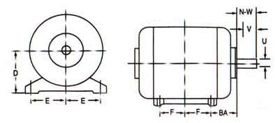
We also need to be aware of the differences between a NEMA frame and an IEC (Metric) frame. IEC motors are usually smaller and more compact than a NEMA frame design when we compare HP to HP. If you've been in our industry or worked with electric motors for quite a while, (and are in the USA) you have probably memorized the various dimensional references that are important to you when applying motors to a new or existing application. In NEMA circles, important frame references are U, N, V, D, H, E, BA, 2F, P, and C. But now that we have the IEC frames and ratings, we need to learn the Metric system of dimensional values. So in the chart below we've set the values side-by-side to help you in the transition from NEMA to IEC.
Motor Frame Chart Letter Definitions |
||
Definition |
NEMA |
IEC |
| Shaft Diameter | U | D |
| Shaft Length (Total) | N | E |
| Shaft Length (Usable) | V | E |
| Centerline of Shaft from Base | D | H |
| Diameter of mounting base hole | H | K |
| Looking into the shaft of the motor, from the vertical centerline of motor/shaft, to mounting base hole; left and right | E | A/2 |
| Looking at the side of the motor, from the end of the usable point of the shaft to the first mounting hole. | BA | C |
| Looking at the side of the motor, from the first (front) mounting hole to the (back) mounting hole. | 2F (1) | B |
| Looking at the shaft of the motor, the total overall diameter of the frame, less the conduit box. | P (2) | AC |
| Looking at the side of the motor, from the end of the shaft to the farthest extreme of the motor frame including fan cover if existing. | C (3) | L |
| (1) Caution here. Some manufacturers may drill multiple sets of holes to accommodate multiple frames | ||
| (2) This dimension may NOT be consistent for all manufacturers. | ||
| (3) This dimension may NOT be listed in a manufacturer's frame chart. Motor length may be different. | ||
And while we attempt to NOT lean toward one manufacturer vs. another, in the case of this topic we're going to be rather "manufacturer specific". ABB/Baldor has the IEC and NEMA frame charts on one PDF form. So when you click the link to view the full size chart, it's going to advertise the ABB/Baldor names, and we're using it because it's a pretty complete chart, not because it's a particular manufacturer.
Motor Resources
As a final note to you on the 3-Phase Electric Induction Motor, when you have a chance, we've found a couple resources that we think are pretty good reading. They're educational and from reliable sources. You can click the links below to view them.
Wound Rotor Motor

A Wound Rotor motor is a three-phase motor that has TWO windings, as compared to a "single" winding in a standard "3-phase Induction Motor". The frame (stator) portion of the motor is nearly identical to it's sister motor, the standard induction motor, but in this case, the ROTOR section of the motor also has a winding inserted. The standard induction motor has a rotor that is of a "cage" design, made up of bars of aluminum or copper with rings attached to each end... forming a type of "cage". Thus the moniker, "Squirrel Cage". The cage is then "cast" full of an aluminum alloy. The rotor cage bars and end rings, conduct electricity within itself due to the forming of the magnetic field from the stator.
Our Wound Rotor Motor, with it's second winding has a couple distinct advantages over the standard induction motor. First, the slip rings, with their brushes, have leads attached that are run out to some type of "resistance". If the resistance is "fixed" in value, then the motor will have distinct starting torque, and it's running (rated) speed will be a value that is LESS THAN the design "synchronous speed". The real advantage is that when the rotor winding (through the slip rings and brushes) is connected to a "variable resistor", then as the resistance is changed, the speed and starting torque characteristics of the motor is changed also. Because of the high starting torque available with the wound rotor motor, and the ability to vary the speed, they were (and still are) used heavily in the hoist and crane industry. Some of those applications are being redirected toward the VFD and induction motor. A draw back of this motor is the higher maintenance due to the wear of the brushes and the slip rings. but wound rotors still have their place.
Synchronous Motor
While the engineering and technical folks identify this motor is as a Three Phase Motor, which is why it's mentioned here, we have it more distinctly classified as a "Special" motor and therefore it's included in that topic page of our website. Click this link to go directly to that page.
Hysteresis Synchronous Motor
While the engineering and technical folks identify this motor is as a Three Phase Motor, which is why it's mentioned here, we have it more distinctly classified as a "Special" motor and therefore it's included in that topic page of our website. Click this link to go directly to that page.
Servo Motor
While the engineering and technical folks identify this motor is as a Three Phase Motor, which is why it's mentioned here, we have it more distinctly classified as a "Special" motor and therefore it's included in that topic page of our website. Click this link to go directly to that page.
 Back to Top


