


DC Variable Speed Drives
DC power has existed "forever"! In fact, DC is the type of power that Thomas Edison was using first as the power source for residential lighting in the late 1870s. Around the same time, George Westinghouse was advocating for the use of high voltage AC power transmitted across long distances and using a transformer to reduce the power for residential lighting. The Europeans had been playing with AC power as early as the 1850s. So DC power has been around pretty much since we humans have been playing with electricity. And if you want to open a "can of worms"... research whether a Lightning Strike is AC or DC power! That'll keep you busy for a while.
But DC power can control the speed of a DC Electric Motor very easily. The voltage being fed to the "Armature" (the rotating member of the motor) can be increased or decreased with a corresponding change in rotating speed; assuming the field strength of the motor is maintained constant. The other way to vary the speed is by changing the strength of the magnet field of the motor. Both methods are used in today's DC drives to accomplish the variable speed of a DC motor.
Remember that one of the early sources of DC power was the "battery". Yes, there were generating stations also, but the battery was the early source of DC power before generators were invented. So the battery can be the primary source of DC power to a motor and we can vary the speed by changing the voltage being applied to the motor armature windings. Electric cars now come to mind...! And companies such as TESLA and their battery research has certainly held our attention over the last decade.
DC Motor Basics

Let's address a little bit about DC motors as we begin the details of our controllers.
It was mentioned about maintaining the strength of the "magnet field" of the motor. It is important to note that there are different designs of DC motors with each having different operating characteristics. The "early" DC motors, and many today have a "field" winding (stationary) and an "armature" winding (rotating). These windings are designed specifically to produce a magnetic field. The field winding is "stationary" within the frame of the motor and the armature winding produces a magnetic field that changes state causing the armature to be rotated within the field frame.
A DC Drive produces different voltages to feed these two winding sources. The "field" voltage is normally "steady" and unchanging. Some field voltages might be 90VDC, 180VDC, 150VDC, 300VDC, and others. But they are steady and unchanging. The "armature" voltage, however, is a changing voltage produced by the control board of the drive, triggering the SCR's (or transistors) in the proper sequence to manufacture a varying voltage. This voltage is fed to the "armature" winding through "brushes" that ride on the "commutator" of the armature.
When the motor needs to change speed, the voltage to the armature is increased or decreased by adjusting the pilot signal to the control board, usually by way of a potentiometer. The power system is triggered to change and the voltage to the armature is modified.
One feature of the "wound field" DC motor is that if we are running at "full speed" based on feeding full voltage to the armature and full voltage to the field, but we need a little more speed, it is possible to "overspeed" the motor by "weakening" the wound field voltage a little. By reducing this field voltage, the magnetic field is weakened and the motor will go faster. This is usually accomplished within the drive itself and is a somewhat risky maneuver so it needs to be used cautiously. Weakening the field TOO MUCH may cause the motor to "run away" (overspeed) to the point of destruction.
DC motors come in various configurations. Wound field DC motors are "Series" wound, "Shunt" wound, or "Compound Wound" designs. The last type of DC motor is a "Permanent Magnet" motor. This last type does NOT have an electrical winding to create the magnetic field but instead has a set of "Permanent Magnets" attached to the frame that creates the stationary magnet field. With this type of motor, we can control the rotating speed, ONLY by changing the voltage to the armature.
Shunt-wound and Compound wound are the most common and are used heavily in the printing and extrusion industries. Series wound motors are known for their extremely high starting torque and can be found most prominently in applications like locomotives. They are known as "traction" motors. Permanent magnet motors will be found mostly in fractional and small horsepower applications due primarily to the limited strength of the permanent magnets available for the field magnets.
DC Drives
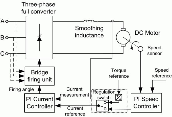

The DC drive is powered (usually) from an AC power source, either single-phase or three-phase. The AC voltage is fed to a "bridge rectifier" (either full or half-wave), and DC power is taken from the positive (+) and negative (-) terminals of the bridge. In ALL cases, there is a distinguishable "ripple" effect in the DC power as the AC voltage goes through its sinusoidal waveform with the voltage of the sine wave changing from 0 to maximum positive, then back to 0, then moving to maximum negative, then back to 0, as it completes it's full AC cycle. This ripple is minimized when three-phase power is rectified since the three-phase legs sort of "fill in" the blank spaces, where single-phase power doesn't have that advantage. To further reduce the "ripple", the rectified DC power is run through a "capacitor-resistor" filter network that nearly eliminates the remaining bumps in the power.
This filtered DC power is what is used to power the DC motor. This filtered power is fed to the power section of the drive to feed the "armature" of the DC motor. The power for the "field" circuit is usually created by a second, smaller, bridge rectifier circuit. That circuit does not have to be as robust since the current drawn by the stationary field is relatively small compared to the armature circuit.
The DC power gets routed to a set of SCR's (Silicon Controlled Rectifiers) that are the power portion of the drive. These SCR's are triggered (told when to turn ON or OFF) by the control board (the brains of the drive). The control board is told "how and when" to trigger the SCR's by the input device, usually a potentiometer, by feeding a control signal to the board. That signal is usually 0-10VDC or 0-5VDC and sometimes, 4-20ma. The Control Board tells the SCR's how long to be "turned on" (conducting current). When the SCR "turns on", it begins to allow the voltage to rise. The longer the SCR's are "turned on" the higher the voltage will rise. When it reaches the limit, as allowed by the control board, the SCR's are "turned off" and the voltage rise stops. This action continues to allow the output voltage from the SCR's to rise and fall (increase and decrease), which feeds the higher or lower voltage to the DC motor armature, and the motor speed increases and decreases.
One of the most desirable features (options) of the DC drive "system", is the ability to change in very small and accurate increments. The DC motor produces a high torque to operate the load but we may want that torque and speed to remain extremely constant due to specific characteristics of the load. In those cases we use "feedback" signals from the driven load (the DC motor) that is compared by the control board of the drive with its input signal... the 1-10VDC, let's say. If the control board finds the two signals differ, it modifies the information being fed to the SCR's, and thus changes the output voltage to correct the signal differential. This keeps the speed of the driven load very constant and allows for precise positioning or resolution of the end product. Such an operation is considered placing the drive and motor in a "closed-loop". The "feedback" devices are a Pulse Generator, Tachometer Generator, Resolver, or Encoder, among the most common.
Another attractive feature of the DC drive system is when we designed the "Regenerative" DC Drive. This drive uses the DC power system and the regenerative power of the motor (during deceleration) to regenerate power back into the drive. One of the prime features of this regenerative feature is to use the power as a "brake". But as technology has progressed, engineers have found ways to regenerate the power back to the incoming power line! So we not only regenerate DC power from the motor back to the drive, but we can convert that DC power back into a 3-phase waveform that can be dumped back into the power grid. Amazing stuff!!!
The drives are now DIGITAL drives, instead of the older ANALOG designs, and the control signal we talked about coming from a potentiometer? Well, factory automation companies, like A.R.&E. are using PLC's and other sophisticated pilot devices to control this DC power in some very inventive and productive ways.
DC motors, drives, and systems, still have a place in the industrial market today. And A.R.&E. can help you make the proper selection for your application.
 Back to Top


