


Industrial Control Pilot Devices
One of the many definitions of the word "Pilot", as defined by "Merriam-Webster.com" states: "...a piece that guides a tool or machine part".
So that's where we begin this topic... a device (piece) that guides (instructs, directs) a machine part.
Pilot devices are "usually" simple things. As simple as a light switch, maybe. Or a push-button, or a limit switch, or a pressure switch, or an electrical contact on a scale. Pilot devices are the "activator" of things that happen!!! We could probably say that without pilot devices, nothing would happen! A pretty drastic remark, but rather accurate, for the most part."
We'll discuss these special little items in a little more detail, just so we can understand better, "How Things Work".
Switches


Switches are probably the more "basic" type of pilot device. A simple "toggle switch" or "light switch" comes to mind. A switch's main function is to perform an "On/Off" type of action, based on the position of the activating arm or handle.
Limit Switches

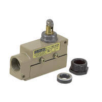

Limit Switches are also an "On/Off" device when it comes to their actions. However, the above mentioned "Switches" are pretty much "manually" operated by you or me, by grabbing the handle and changing its position from On to Off or Off to On. The limit switch is different, AND, its name gives away it's normal function.
A Limit Switch is activated by some "mechanical" means, like maybe a piece of plate steel attached to the end of a conveyor frame. The limit switch is mounted at the end of that conveyor so that when a particular part of the conveyor reaches that point, the plate mounted on the conveyor will strike the limit switch lever and transfer its position from "Off to On" or "On to Off", as the control scheme requires. Once the plate has passed the limit switch, if the lever is released, it returns to its normal position, resetting the control scheme for the next cycle. A simple application is a "counting" scheme where each time the limit switch is activated, it sends a signal and a counter is advanced.
Limit switches have numerous "levers" or activation devices on them. Some levers have an adjustable length, others are a "roller", some are called a "whisker" (very flexible longer wire), and others have special activators. The design of the common limit switch is somewhat standardized and additionally today, rather than a lever head with an activating lever, the top head can be replaced with a "proximity sensing" head so that the activation does NOT have to touch anything. It simply passes by and activates the "proximity sensor". Limit switches (and hybrids of them) are key to controlling moving production lines.
Push Buttons
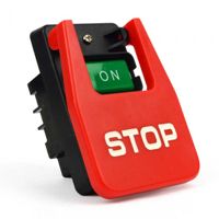


Here we've come to the grand-daddy of all pilot devices! The "Push Button"!!!
This is probably the most heavily used pilot device in existence. They come in basically two (2) configurations... Momentary and Maintained. The explanation being, momentary is one that when you press the button and then release it, the button returns to its initial position. The maintained design is just that... when you press the button and remove your finger from the button, the action REMAINS in the newly activated position. Both have their place but the momentary is by far the most heavily used design, and for reasons we'll address a little farther on in this section.
The pushbutton comes in about a "gazillion" configurations, but they all do the same thing. When pressed (either by an operator's finger or some other mechanical means), the action causes an electrical circuit to be opened or closed, to activate some operating device, like a motor starter, to energize (or de-energize) and cause a motor to run (or stop). That's it! That's all they do.
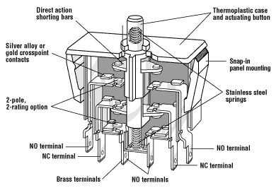
The button that is pressed, is mechanically attached to a plunger which has a mechanical attachment to a crossbar that holds a "moving" electrical contact that will "bridge" the stationary contacts of the pushbutton housing. If you've read our explanation of an "Electrical Contactor", you'll remember that we discussed how the power poles of the contactor and crossbar move to complete the power circuit of the contactor. The pushbutton does the same thing except it is dealing with a much lower power rating (usually 10 amps or less), as compared to the contactor dealing with possibly hundreds of amps. And of course, the voltage rating too. Pilot devices, like pushbuttons, are normally rated for lower voltage like 120VAC or 24VDC, rather than the power side that may be rated at 480VAC or 600VAC or higher.
As we've said, there are numerous types of pushbuttons but with today's designs, a high majority of the designs have "stackable" contact blocks. This simply means that by stacking contact blocks, you can operate multiple pilot circuits with the press of ONE button. Like starting more than one motor at a time. Or starting a motor with one contact and operating a timing circuit with another.

But here's a NOTE OF CAUTION for you... due to the inherent "slop" or tolerances in the movement of the plunger and crossbar on the pushbutton contact blocks, if you stack TOO MANY you may run into a situation where the contacts farthest from the button surface may NOT move sufficiently to close the contact and activate the appropriate circuit on a consistent basis. Check with the manufacturer to see what they recommend as the maximum number of contact blocks to stack. The photo above, MAY NOT WORK!!!


Finally, pushbuttons as we've described them, have been outlined as "individual" items. But they come in assembled configurations, too. Like crane control pendants with multiple directional buttons for controlling overhead cranes in your shop. Or a control station that holds the pushbuttons and pilot lights for a complete production line. Or even the TV or Radio station console...! And think of it... even the newer automobiles are going back to push buttons to start the vehicle, and using push buttons to select the transmission options. So don't just think of them as pushbuttons... these are true Pilot Devices.
Selector Switches
Selector Switches are "pushbuttons" in disguise! They pretty much do the same as a pushbutton, or other pilot devices, except in this case you get to choose... "Select" what you want to do... i.e. "Selector Switch".


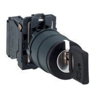
In thinking about pushbuttons vs. selector switch, we look at the action. When you rotate the lever (handle) of the selector switch, the action performed closes a set of contacts, which in turn, closes the main circuit to power some device and operate some machine. And like the pushbutton, you can get them in Momentary or Maintained contact configuration. By and large, the majority of selector switches are Maintained, in nature, but the momentary ones are certainly rather common. The "momentary" action comes from a feature in the selector switch mechanism that has a "spring return" from a selected position, back to the normal position of the handle. And further hybrids use "keys" to operate them for security purposes. You've probably seen things on TV or the movies, like nuclear launches where 2 keys have to be operated to complete the launch. That's where a key operated selector switch comes in.
But the description above is talking about the "pilot device" design of the selector switch. A "power" type of switch is manufactured where you can operate a motor DIRECTLY with the selector switch. These are usually "reversing" or "multi-speed" devices and are limited to smaller horsepower motors.

Instrument Selector Switches


And finally, instrument type "rotary selector switches. These are switches used to allow an operator of a control station to "select" or verify the Voltage and/or Amperage of devices (loads like motors) that are critical to the operation of the plant. The switches are multi-contact devices and are usually maintained contact in their positions. A voltmeter switch will have positions to read phases A to B, B to C, C to A, and Off. While an ammeter switch will have positions to read phases A, B, C, and Off. They are a specialty switch, but still a simple "Selector Switch".
Specialty Pilot Controls
In this section, we'll touch on some specialty controls that we maybe haven't talked about directly, but maybe skirted around them in passing.
Light Curtains


Light curtains are a special item used heavily for the Safety of operators of operating machinery, as well as other purposes. It's a little difficult to say just when a light curtain should be used, but suffice to say, their action is to shut down a piece of equipment, or maybe sound a loud alarm, or flash a gazillion bright strobe lights, if the light curtain line of protection is broken. Like if the machine is running and someone extends their arm through the light curtain... BAM! The alarms are triggered!
Proximity Sensors


We talked about proximity sensors in the paragraph on Limit Switches, but just in passing. Proximity Sensors (Prox Switches), are of a couple of designs. One of which is an Inductive Proximity Sensor and the other is a Capacitive Proximity Sensor. They each have their place in control schemes but operate very differently.
Using my Wikipedia.org source, again... the information is as follows:
A proximity sensor is a sensor able to detect the presence of nearby objects without any physical contact. A proximity sensor often emits an "Electromagnetic Field" or a beam of "Electromagnetic Radiation," (infrared, for instance), and looks for changes in the magnetic field or return signal.
The item being sensed is often referred to as the proximity sensor's target. Different proximity sensor targets demand different sensors. For example, a "Capacitive Proximity Sensor," might be suitable to sense a plastic target; but an "Inductive Proximity Sensor," always requires a metal target.
Proximity sensors can have high reliability and long functional life because of the absence of mechanical parts and lack of physical contact between the sensor and the sensed object.
Proximity sensors monitor machine vibration to measure the variation in distance between a shaft and its support bearing. Monitoring, for this purpose, is a common practice in large steam turbines, compressors, and motors that use sleeve-type bearings.
A proximity sensor adjusted to a very close range is often used as a "Touch Switch." That's what makes your cell phone touch system work... or the touch screen in your vehicle or on your laptop.
A Capacitive Sensor works well in non-displacement applications, where things aren't moving around a lot. Some of these applications include testing the moisture of grain in a grain silo, checking soil moisture, checking humidity, detecting water in fuels, and capacitive load cells in scales, to mention just a few.
Conversely, the Inductive Sensor works when a "METAL" target passes close to the sensor body. In the case of an inductive proximity switch, a magnetic field is generated out from the face of the sensor. When metal passes through that magnetic field, a change in the field produces an electrical current. The sensor circuitry reacts to that change in the field to produce an action. One significant application is the buried "inductive loop" of wire in the pavement near traffic signals. When a vehicle passes over the wire, the field changes, sensing the vehicle and triggering the traffic signal controls to prepare for a change of state. The controls, of course, have timers, relays, and PLCs that control when the traffic lights change. But the inductive loop to the proximity sensor is the "Pilot Device" that puts everything into motion. Think about how an inductive proximity sensor picks up the presence of metal the next time you're looking for buried treasure at the beach!
Proximity Sensors are a key pilot device in today's more automated world.
Control Power Sources
This is the final section of our "Pilot Device" topic and possibly a little strange to be included as a Pilot Device.
The control power has everything to do with the circuitry and operation of these pilot devices. We talked a little about pilot devices being for lower voltage applications rather than the power side. So let's look at what these devices have to offer.
First of all, let's all remember that you can "transform" AC electrical power but NOT DC! That's an important fact that you've got to know. So if we want "low voltage" control power as AC power, we can use a "control power transformer." But if we need "low voltage" control power as DC power, we need to have a "DC power supply." Let's talk about the differences between the two.

An AC Control Power Transformer is a device that has two separate electrical windings wrapped around a laminated iron core. The mechanical number of turns of wire in the two windings will be a "ratio" that offers us the voltage that we want. The high voltage winding is the "Primary" winding, while the low voltage winding is the "Secondary" winding. When these transformers are manufactured, the primary and secondary windings may be "tapped" to allow multiple voltages to be applied to the primary or taken from the secondary. These taps are very convenient when we're not sure of the incoming power to the control circuit. For instance, a transformer primary tap might be for 480VAC or 240VAC, and the secondary could be for 240VAC, 120VAC, and 24VAC. Some designs have fuses on the primary and secondary circuits making a very compact package.
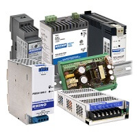
The DC Power Supply is normally a "solid-state" device containing diodes and rectifiers, along with some capacitors and resistors. The circuit design within the unit allows the incoming power to be, say, 240VAC with an output of 12VDC, or 24VDC or 48VDC. It may also be designed to allow the incoming power to be multiple voltages, also. Like 120VAC, 240VAC, and 480VAC. DC power supplies are normally protected from overload by monitoring the current output and heat generated by the package.
These devices allow the panel builder to have the power side of the panel be at a higher voltage (240VAC, 480VAC, or 600VAC) while the control circuits are designed and operated at a much safer 24V, 48V or 120V volts.
 Back to Top


